What we'll do today 🛠️
Last session you met your car and drove it. This session you build one! Don't worry — you won't have to remember anything. Your kit comes with a printed manual and there's an official video that show every single screw. The manual is your turn-by-turn map; this page is the big picture: it splits the build into a few friendly milestones, shows you what each finished chunk should look like, and points out the few tricky spots where you'll want to slow down.
Here's where we're headed — a fully built car, ready to roll:
What you need
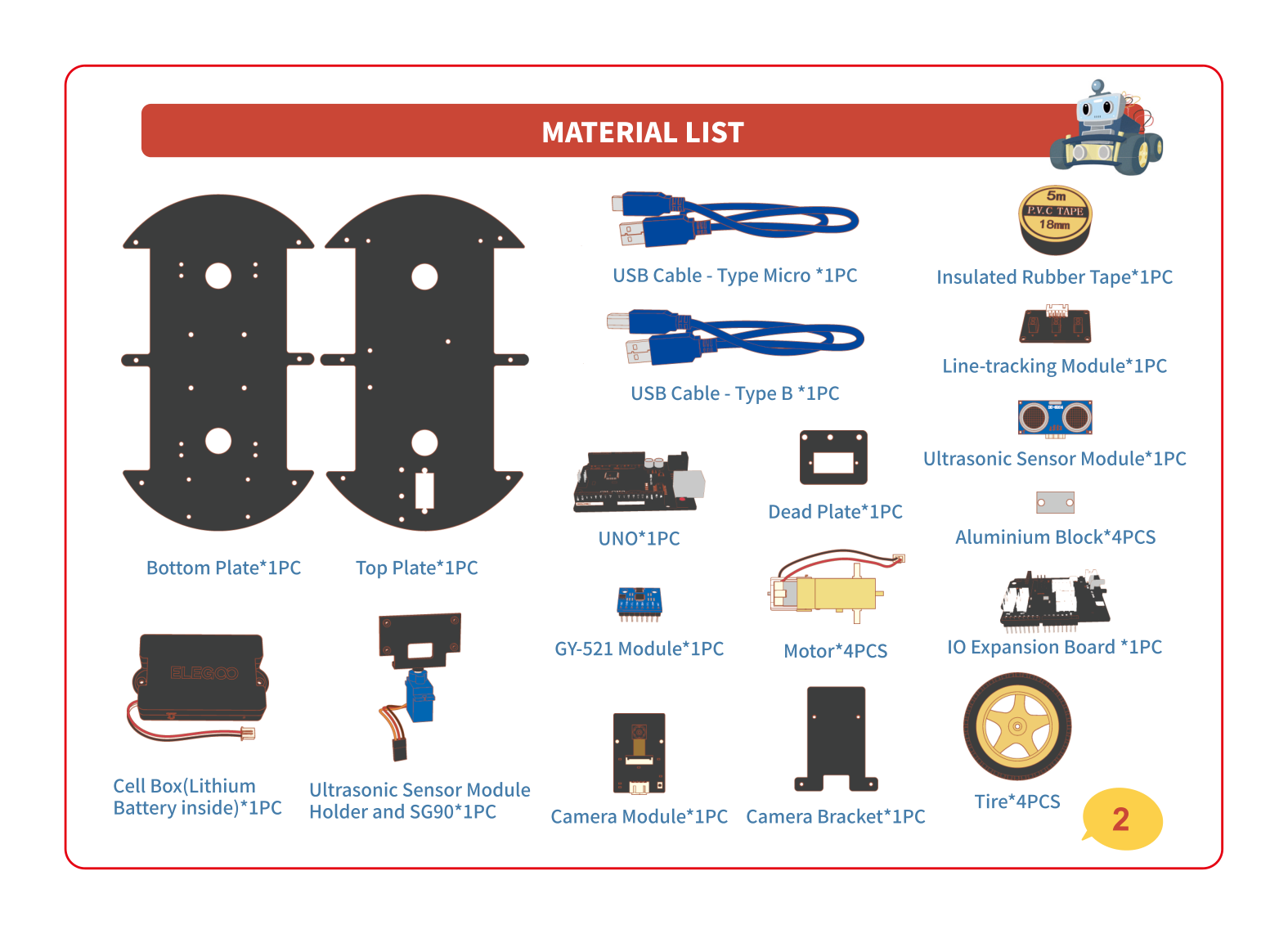
Tip your kit out and find these. Most parts come in little bags labeled for the step they belong to (like "FOR MOTOR" or "FOR CAMERA") — keep them closed until that step!
- The two big black plates (the bottom plate and the top plate)
- 4 yellow motors and 4 big tires
- The boards — the UNO and the IO expansion board — and the little GY-521 chip
- The sensors — line-tracking module, ultrasonic "eyes", camera, and the blue SG90 servo
- The black battery box with the ELEGOO label
- The labeled bags of screws, nuts and standoffs, plus the included screwdriver
- Your printed manual (and a grown-up nearby for the tiny screws)
Build it, milestone by milestone 🚗
Eight chunks, in order. Each one shows the finished look, names the part it adds, and tells you where to find that moment in the official video. Follow your paper manual for the exact screws in between.
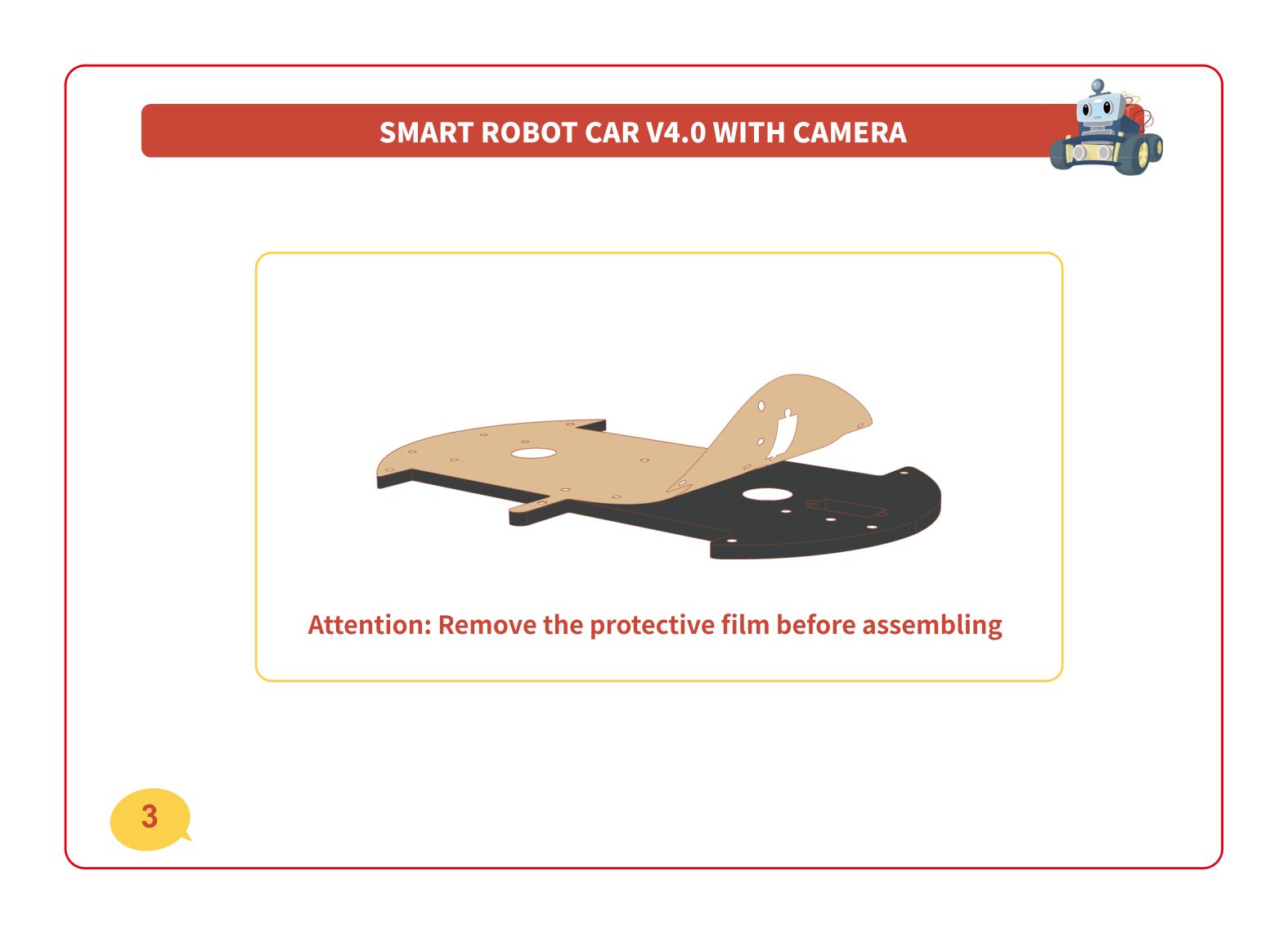
🧩 Lay out the parts & peel the film
Spread all the parts out so you can see them. Then look closely at the two big black plates — they're wrapped in a thin protective film. Peel it off both sides of both plates before you build anything. It pulls off like a sticker.
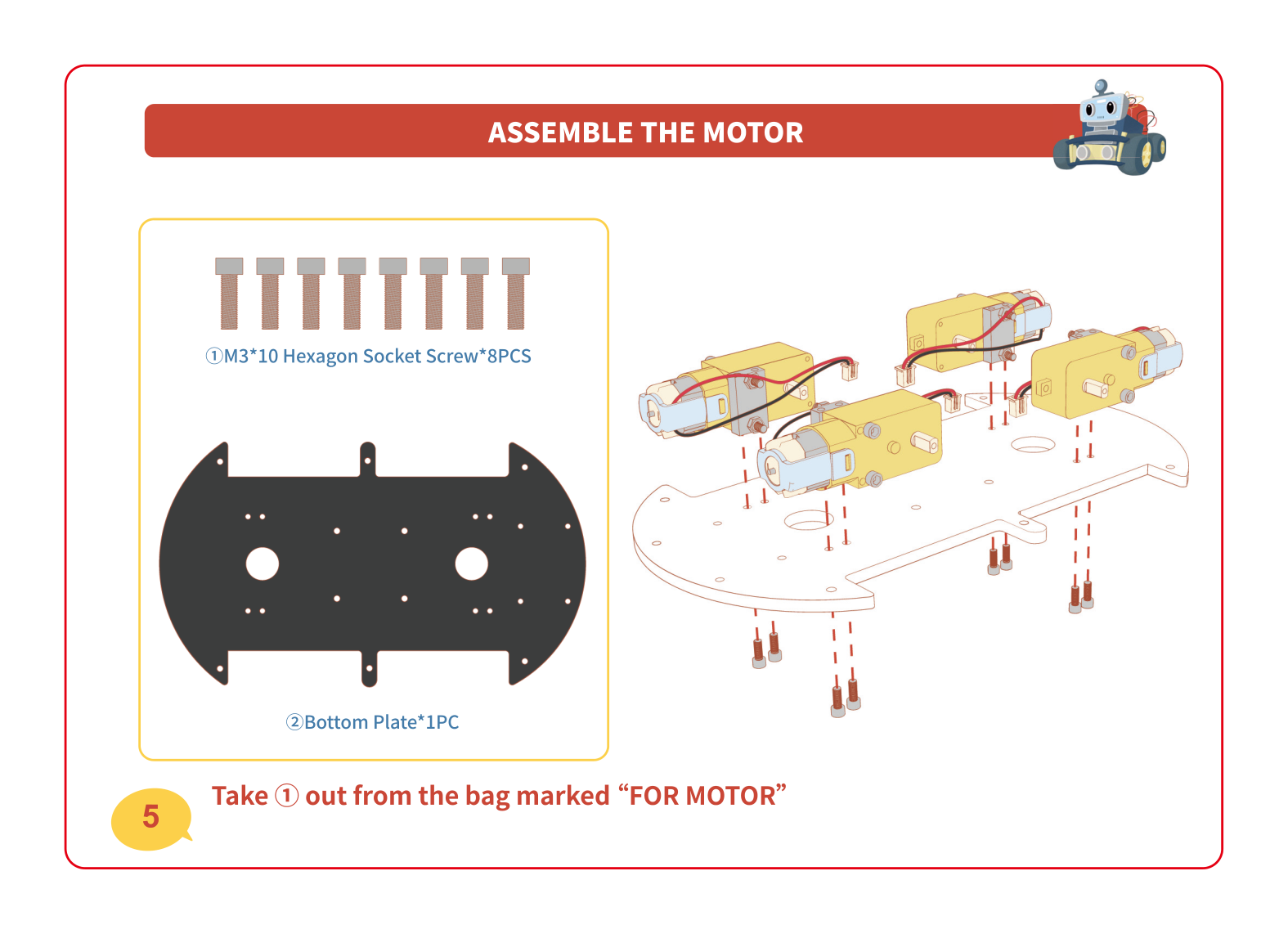
💪 Motors + wheels — the muscles
Each yellow motor is a tiny muscle that spins one wheel. You'll bolt all four motors to the bottom plate, facing outward, using the long screws and the little aluminium blocks from the bag marked "FOR MOTOR". The red and black wires should point inward so you can plug them in later.
👀 Line-tracking module — the floor-watcher
Flip to the bottom plate and add the line-tracking module — the little board with three eyes that face the floor. It uses short pillars (standoffs) so it hangs just above the ground, ready to spot a black line later. Parts come from the bag marked "FOR UNO, LINE TRACKING".
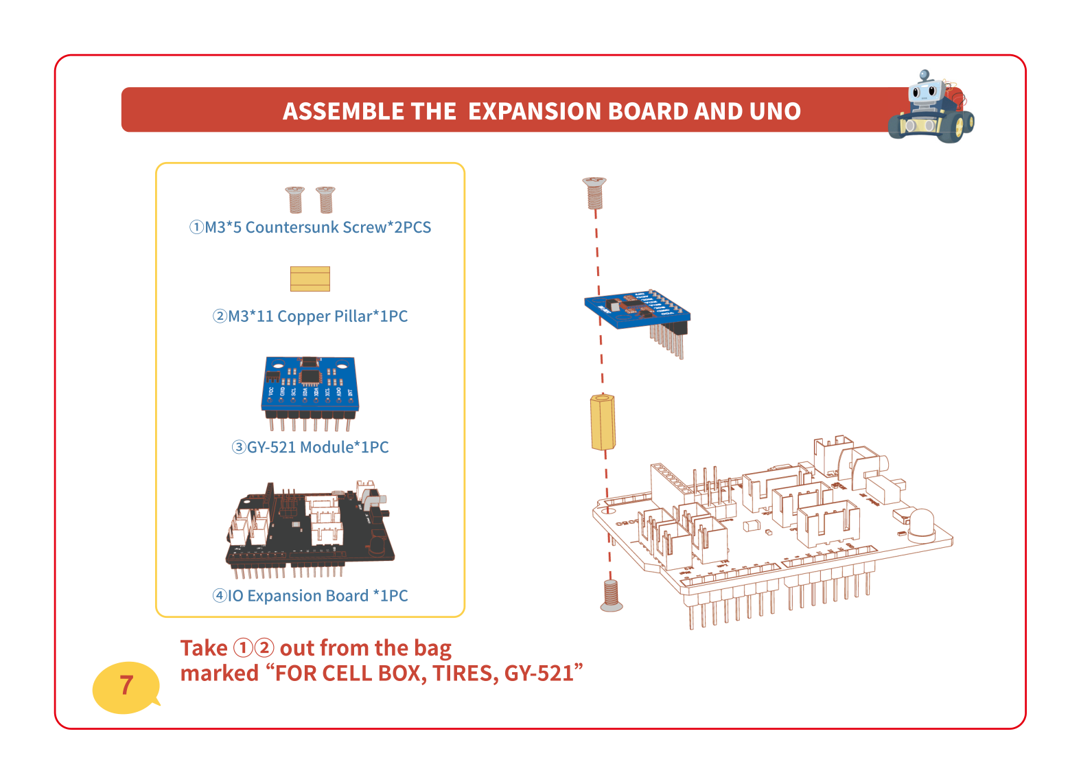
🧠 The boards — the brain
Now the brain! First clip the tiny blue GY-521 chip onto the big IO expansion board — that chip is the car's sense of balance (it knows which way is up and which way is straight). Then mount the expansion board, and stack the UNO underneath. Together these are the computer that runs everything.
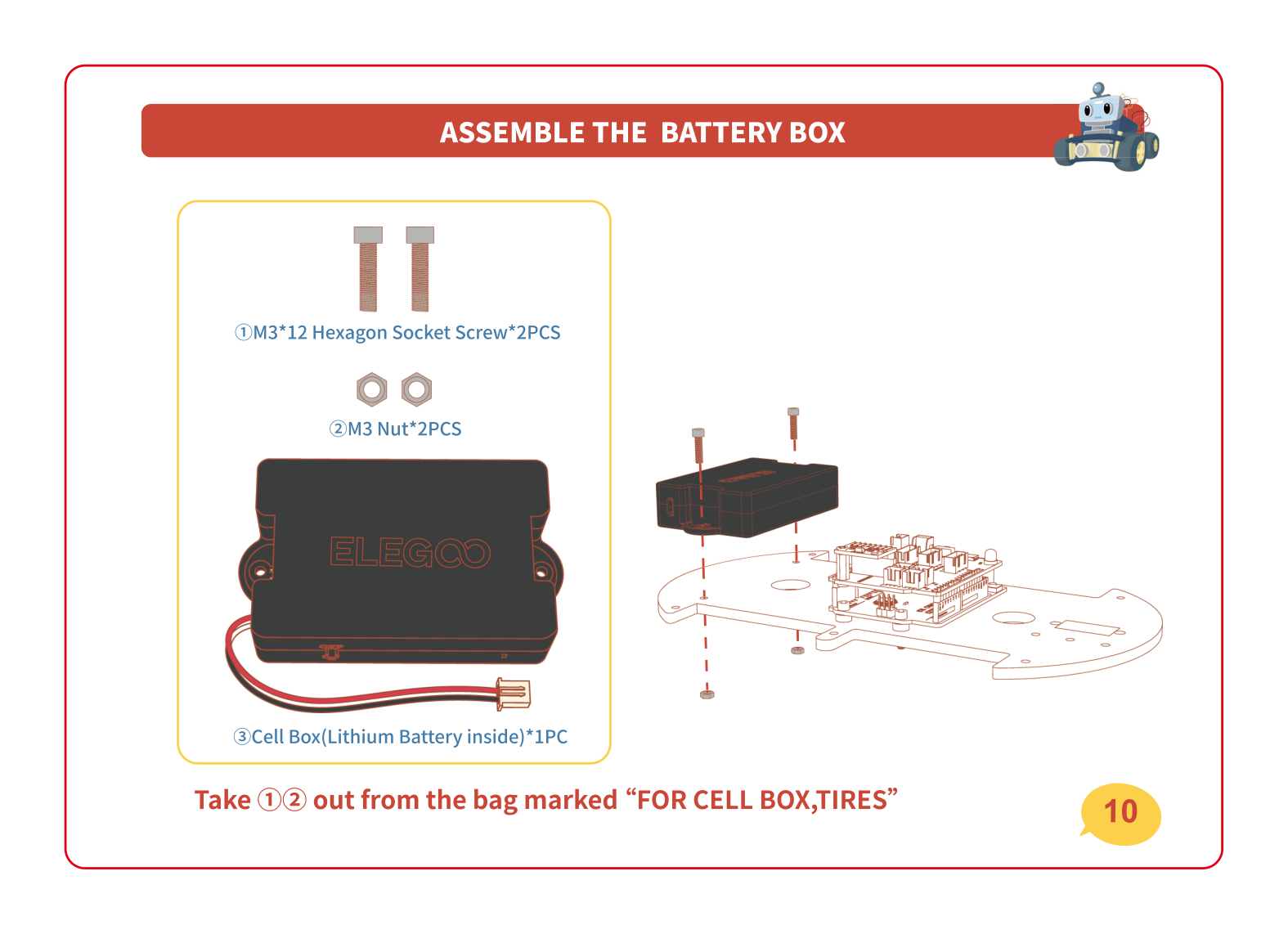
🔋 Battery box — the heart
Bolt the black battery box (the heart) onto the chassis with two screws and nuts from the bag marked "FOR CELL BOX, TIRES". This is what powers the whole car. Leave its wire loose for now — we'll plug everything in during the wiring step.
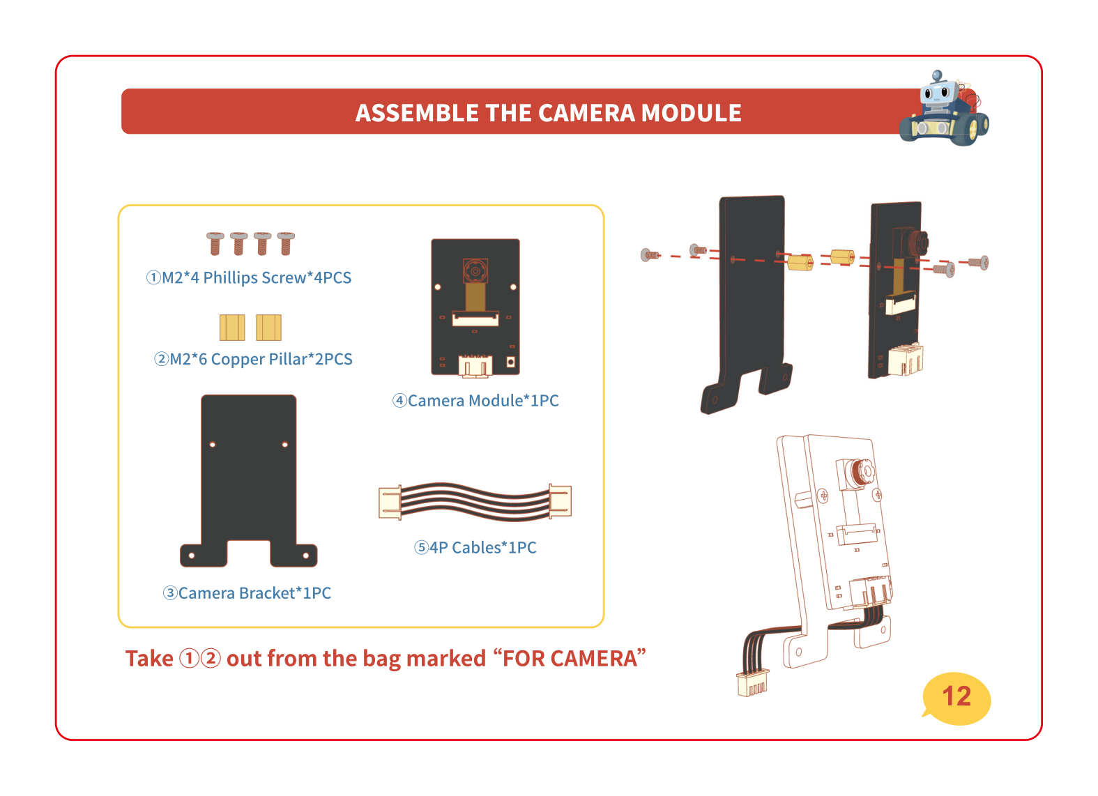
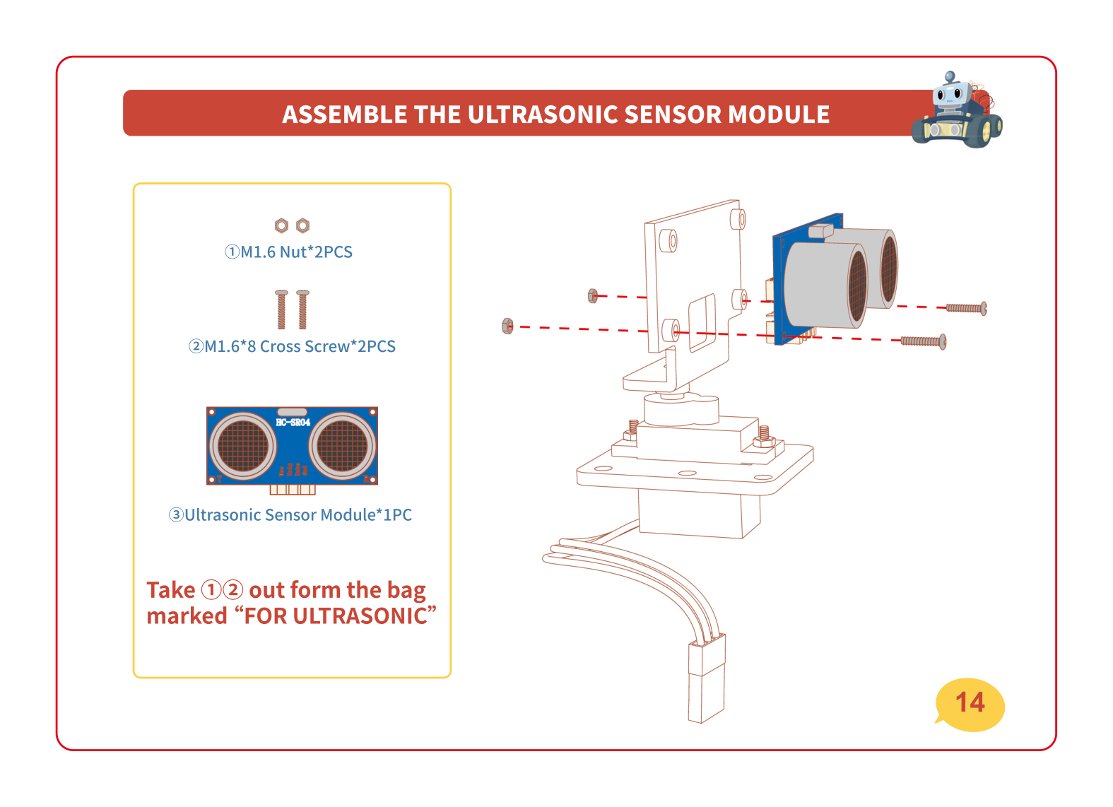
👀 Camera, ultrasonic & servo head — the eyes
Time for the eyes! Build the camera onto its bracket, then add the ultrasonic sensor (the part that looks like two round eyes) on top of the blue SG90 servo. The servo is a little motor that lets the head turn left and right so the car can look around.
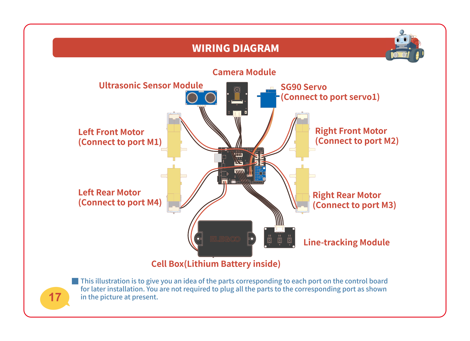
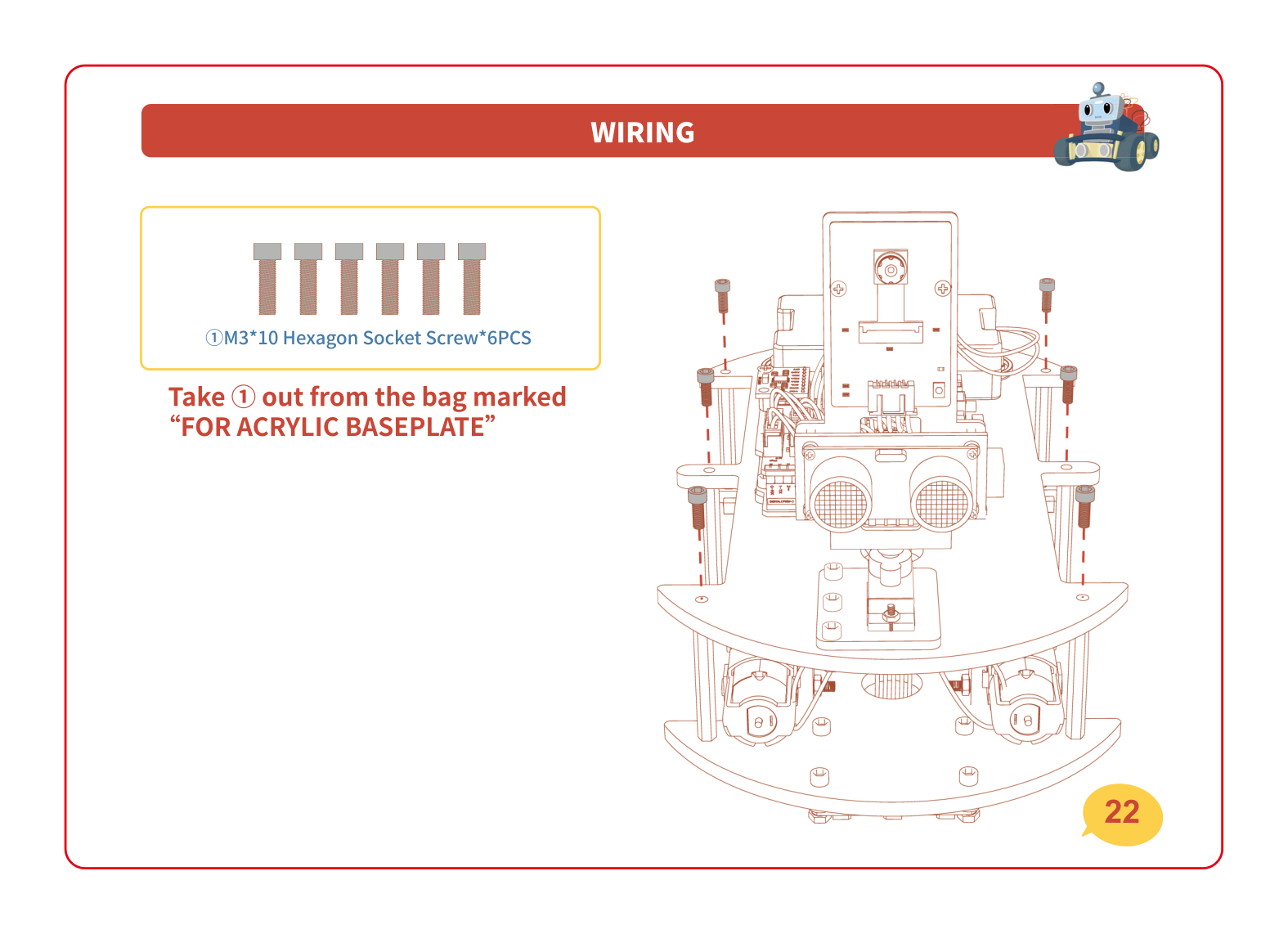
🔌 Wiring the cables — connect it all up
Now plug everything into the brain board: the four motors, the line-tracking module, the servo, the ultrasonic sensor and the battery. Each cable has a labeled port on the board. The picture below is your map of which plug goes where.
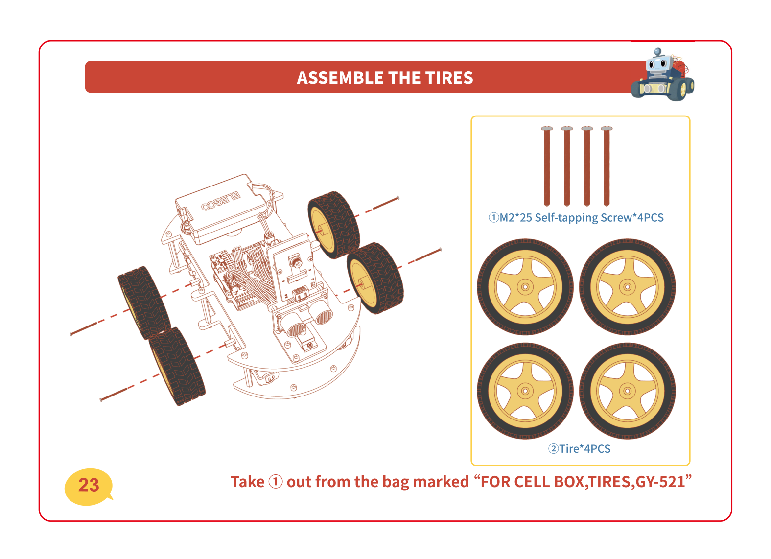
🏁 Join the two plates + add the tires
The home stretch! Stand the tall copper standoffs on the bottom plate, then lower the top plate on and screw it down — now your car has two decks. Finally, push the four big tires onto the motor shafts and lock them on with the self-tapping screws. Tuck any loose wires inside as you close it up.
If something's not working
A motor won't sit flush against the plate
Something is usually caught underneath — check that the little aluminium block and the motor's wires aren't pinched between the motor and the plate. Loosen the screws, wiggle the motor so it sits flat, then tighten again evenly (a little on each screw, back and forth) so it doesn't end up crooked.
A cable plug won't push into its socket
Don't force it! The plugs are keyed, meaning they only fit one way. Look at the little notch or shape on the plug and line it up with the socket, then press gently and straight down. If it still won't go, you're probably at the wrong port — check the wiring map above and find the matching label.
I have leftover screws at the end
A few spare screws and nuts in the kit are totally normal — manufacturers add extras in case one rolls away. But if you have a lot left, flip back through the manual and check each milestone: a missing screw usually means a part is loose. Give the motors, boards and sensor head a gentle wiggle to make sure nothing is wobbly.
The plates won't close up — something's in the way
It's almost always a cable. Before pressing the top plate down, gently tuck the wires toward the middle so they sit between the decks instead of poking out. Make sure no plug is squashed against a standoff.
Level up 🚀
Charged and built? Power it on — that was Lesson 1: set it down flat, slide the switch to ON, and let it find "straight". Walk around your finished car and find all four parts again: 🧠 brain, 💪 muscles, 👀 eyes, 🔋 heart. Next session you'll drive it — and soon you'll teach it to follow a line and dodge obstacles all by itself. You built a robot. That's a big deal! 🎉